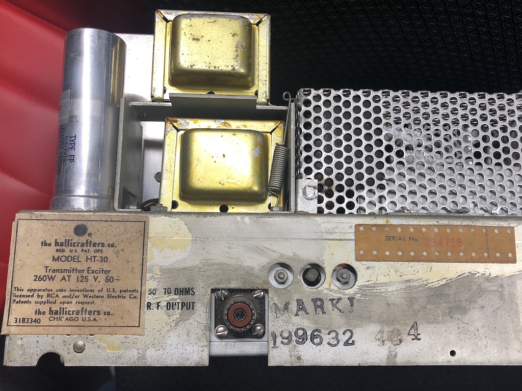
Haliicrafters HT-30
Kihwal Lee (K9SUL)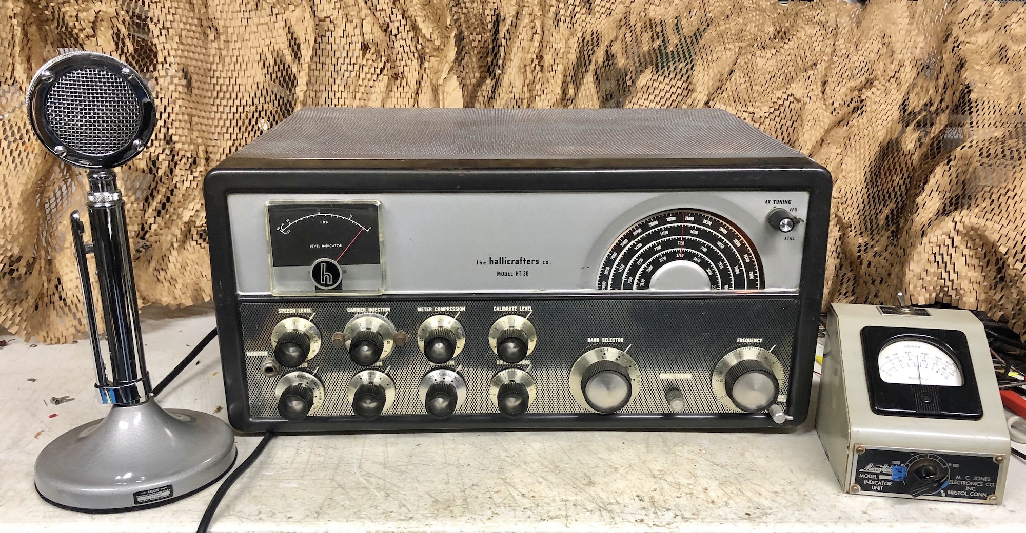
The HT-30 was the first sideband transmitter by Hallicrafters. It was released in 1954, which is quite early for amateur SSB communications. A lot of exciting early experiments were going on at that time for both phasing and filter type sideband transmitters. The first commercially successful amateur sideband transmitter products were from Central Electronics and the 20A transmitter was popular among the early adopters of 1954. The KWS-1 AM/SSB/CW transmitter, the tranmitter of the gold dust twin, by Collins came out in 1955. Clearly, the HT-30 was one of the earliest complete bandswitched SSB transmitter with internal VFO at that time.
It is interesting that Hallicrafters first tried the 50kHz LC filtering for SSB generation in this transmitter. Apparently some commercial units were already utilizing this technology. I have seen a big 50kHz LC filter module for Hallicrafters commercial units, but not sure what kind of equipment it was for. Another source of such a filter was Barker and Williamson. BW manufactured and sold 17kHz cf, 3kHz bw LC filters. BW 360 was for receivers and there was a separate product for transmitters too.
The HT-30 uses a pair of 6BY6 (similar to 6BE6) as a balanced modulator to generate DSB signal at 50kHz. This goes through a series of LC filters and a 6BH6 buffer amps to suppress the unwanted sideband. The B.M. suppresses the carrier at least 20dB (much more if alignment is not drifting) and the filter chain further attenuates it by at least 30dB. Sideband suppression is better than 40dB. The 50kHz modulated signal is mixed with 1675kHz or 1775kHz xtal osc output to generate 1725kHz LSB or USB signal. A simlar mixing scheme was later used in the HT-32 transmitter. The 1725kHz signal is then mixed with a band xtal osc output, then with the VFO output. For 10m, the VFO signal is quadrupled (4x) and mixed. After the 6CB6 buffer and the 12BY7 driver, a pair of 6146 is used for final amplification. Unlike typical configurations found in later 100W class transmitters, the HV is set to 400V and the screen at 190V. The parameters are exactly same as the ones found in the early RCA datasheet of 6146. This was for CCS, not ICAS. So, as far as the final amplifier is concerned, it can run at 100% duty cycle for a long time. The power output is 30-40W.
Rapiring and restoring HT-30
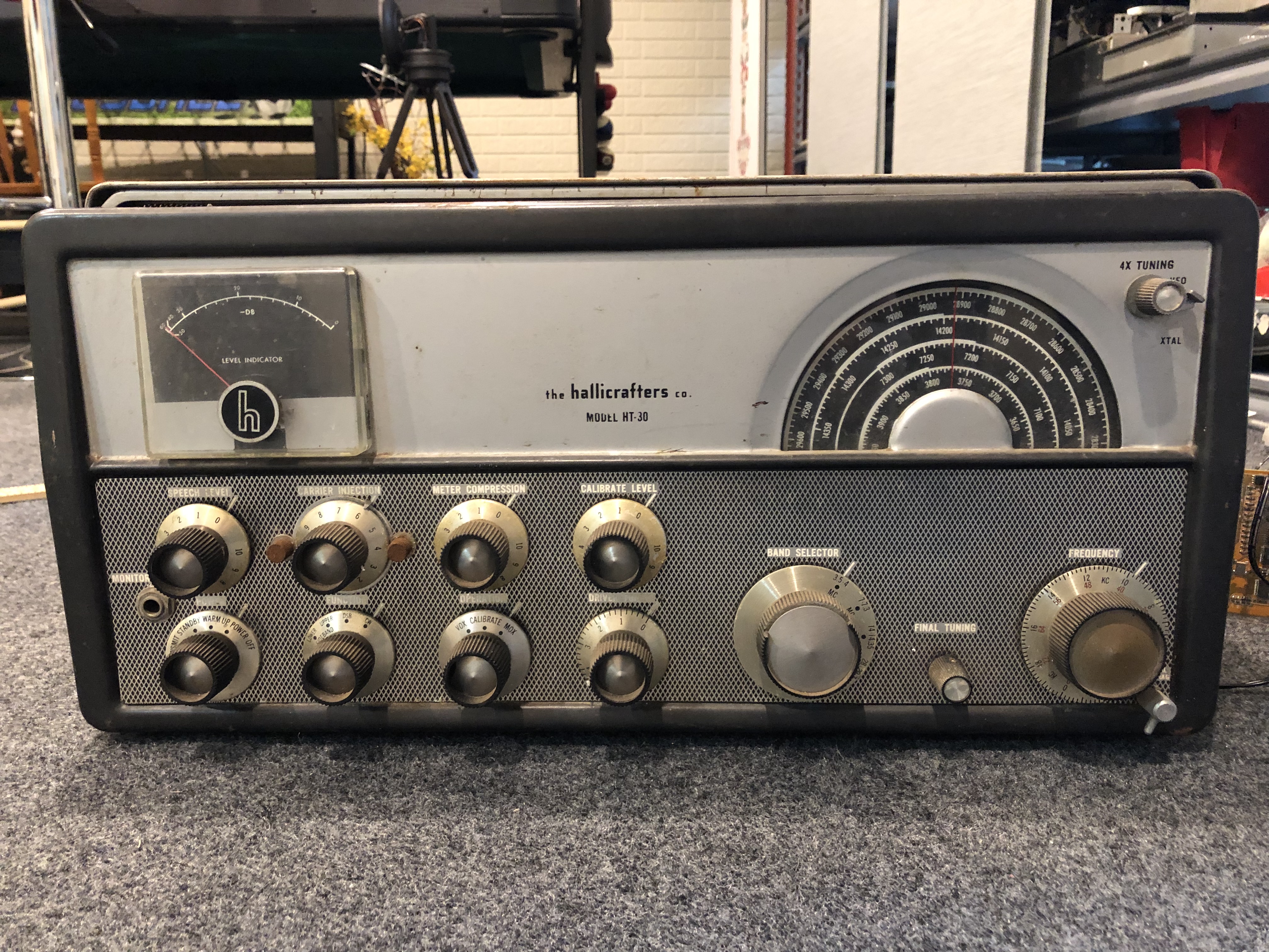
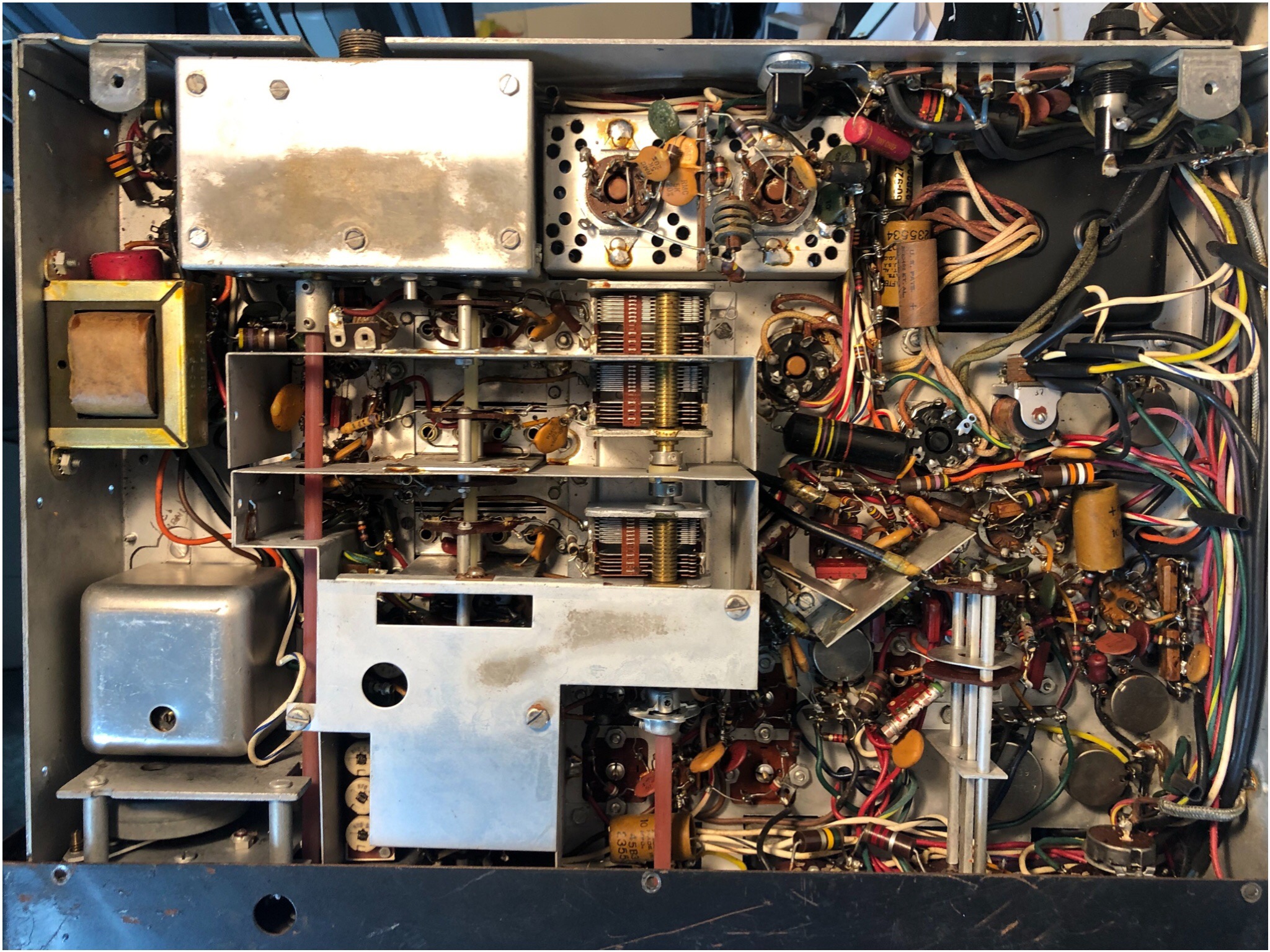
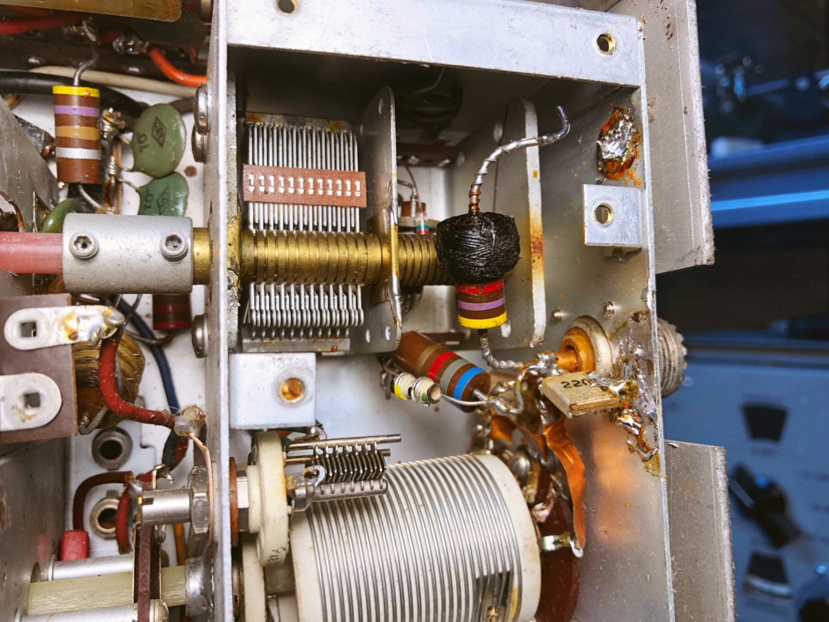
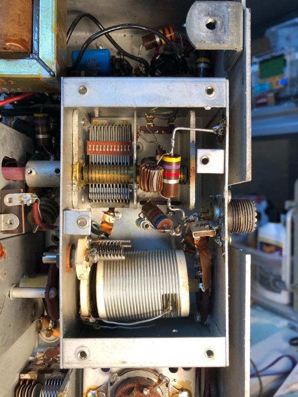
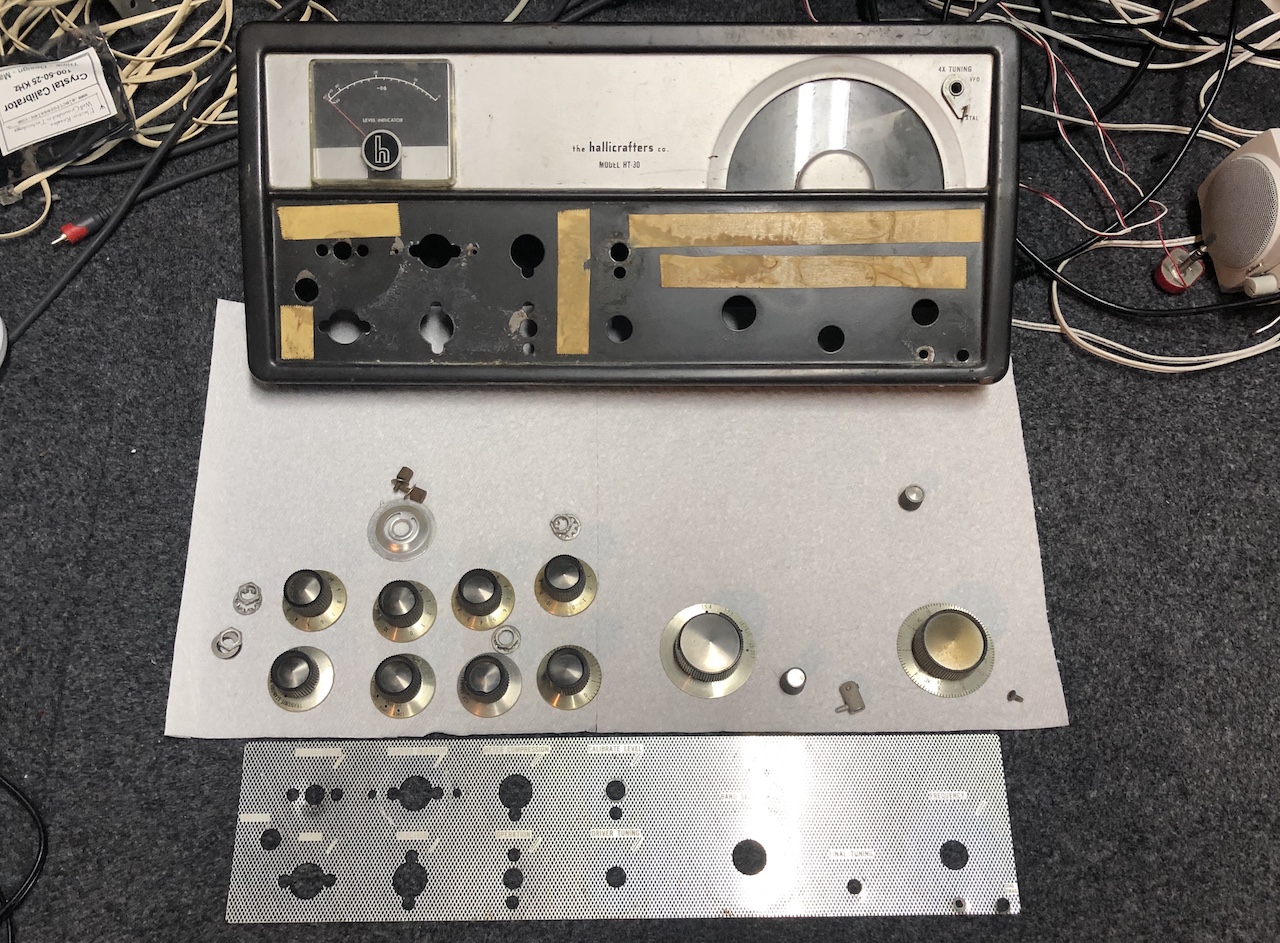
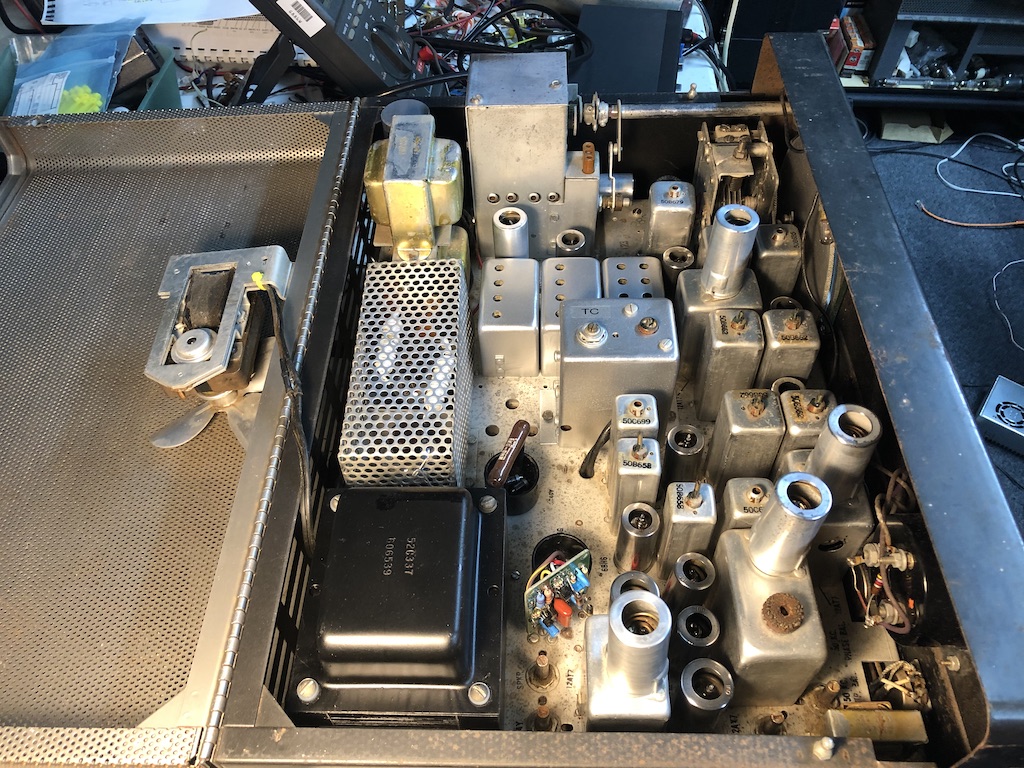
The following three pictures show the condition before restoration. Other than some corrosion, there was nothing seriously damaged.
Click to view larger image

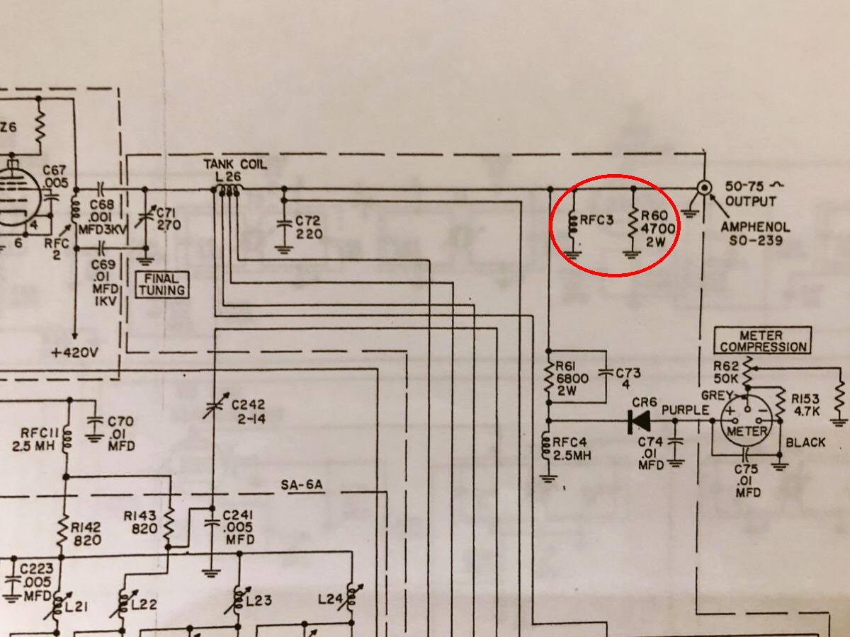
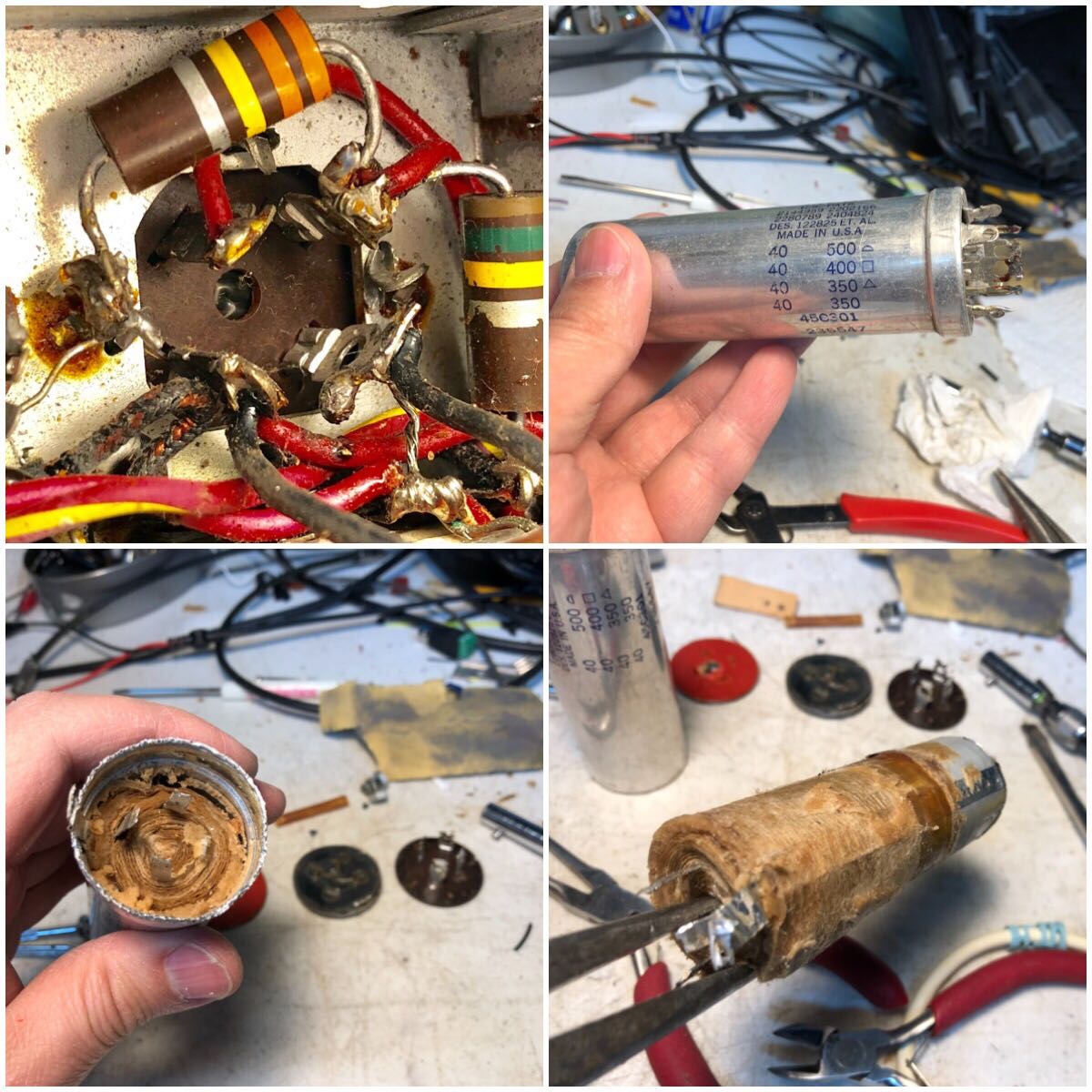
Noticed a choke in the final cage was burnt. It was wound on a resistor. Ended up replacing with a coil wound on a toroid.
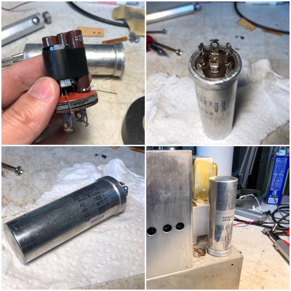
Original 40uF 500V, 400V, 350V, 350V.
New 47uF 500V, 450V, 450V, 450V.
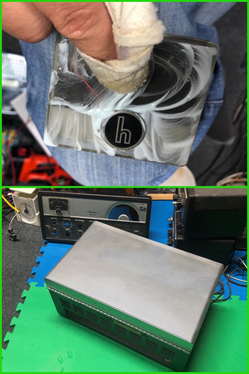
Cleaning and re-painting the cover. The meter cover was polished and the tube shield were cleaned.
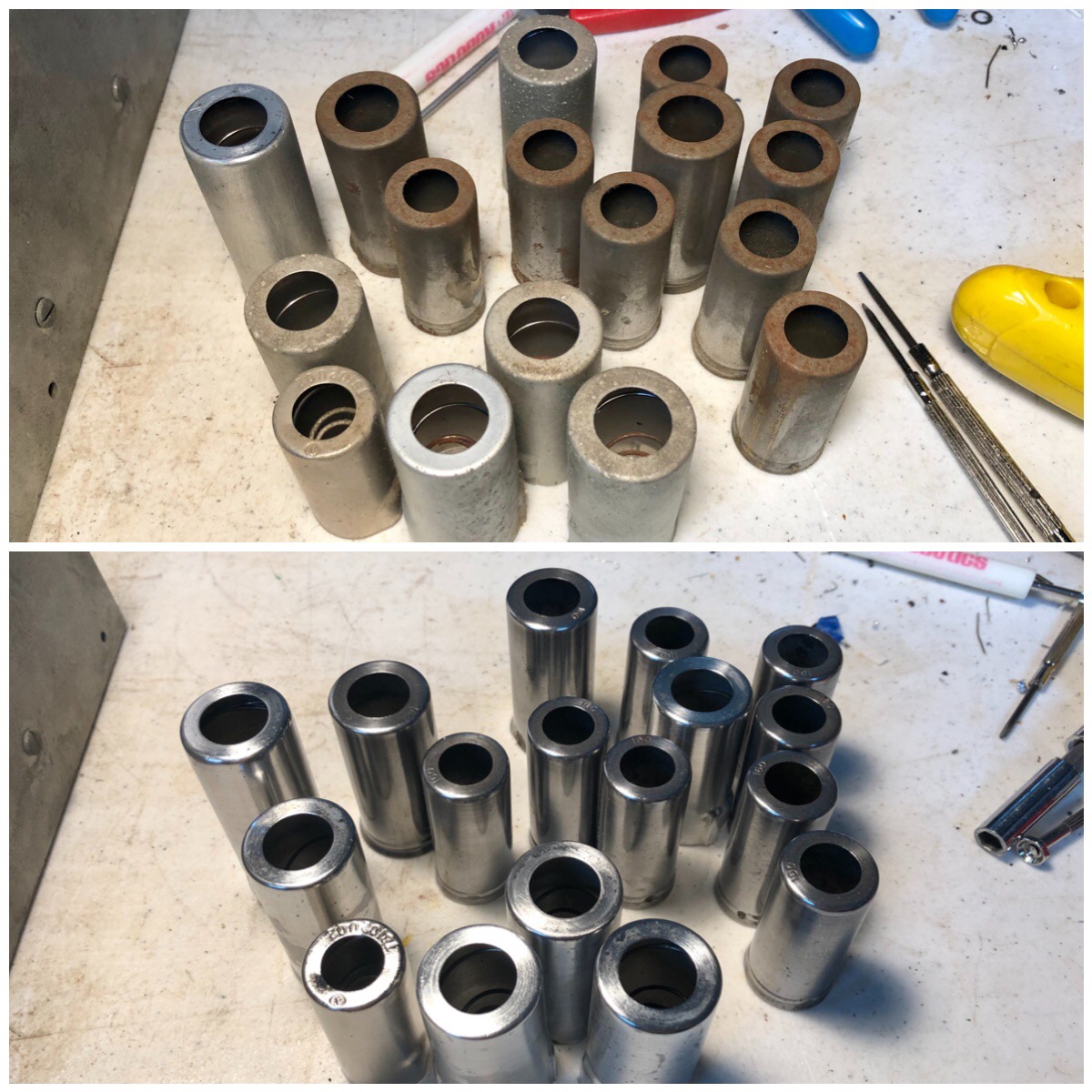
Tube shields before and after.
Putting things back together after cleaning.
In the middle of curcuit troubleshooting, it started blowing fuse. It turned out the primary winding in the power transformer was shorted. I cosidered many options including rewinding the transformer, but settled with a similar one from Hammond, the 300BX. In order to use the new transformer, I changed the wiring a bit and transplanted the bell covers. The core size was identical, but it was slightly thicker. No problem in physical mounting. The main problem was its lack of LV winding.
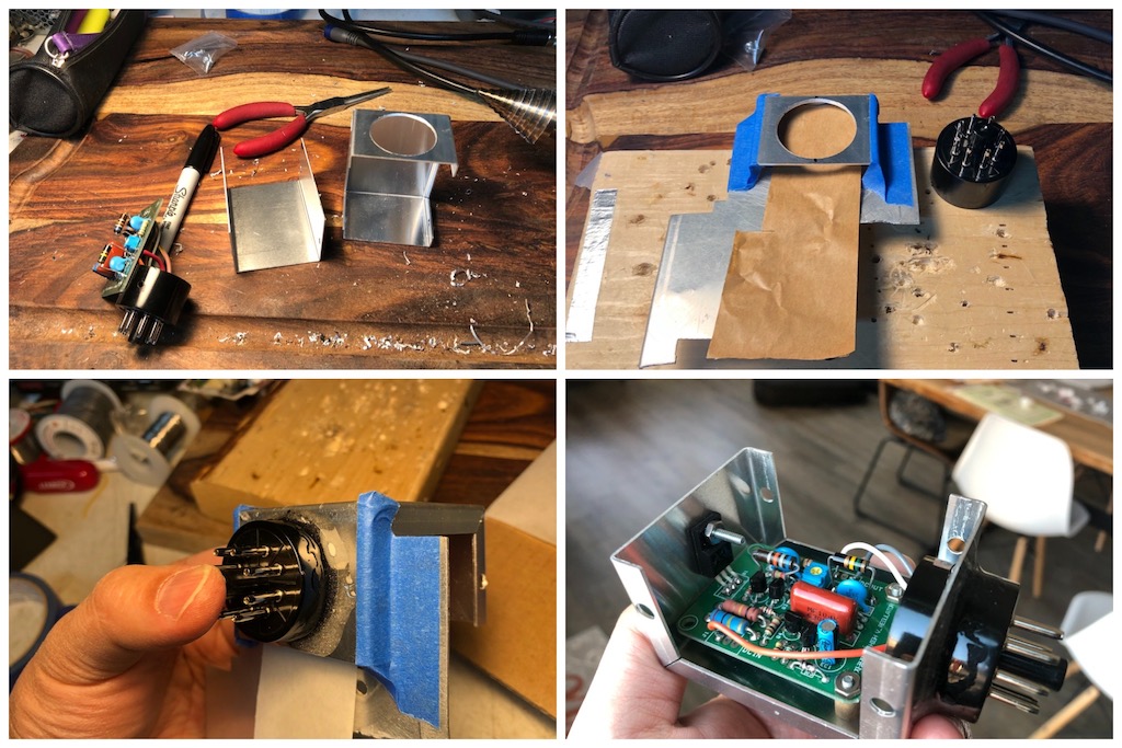
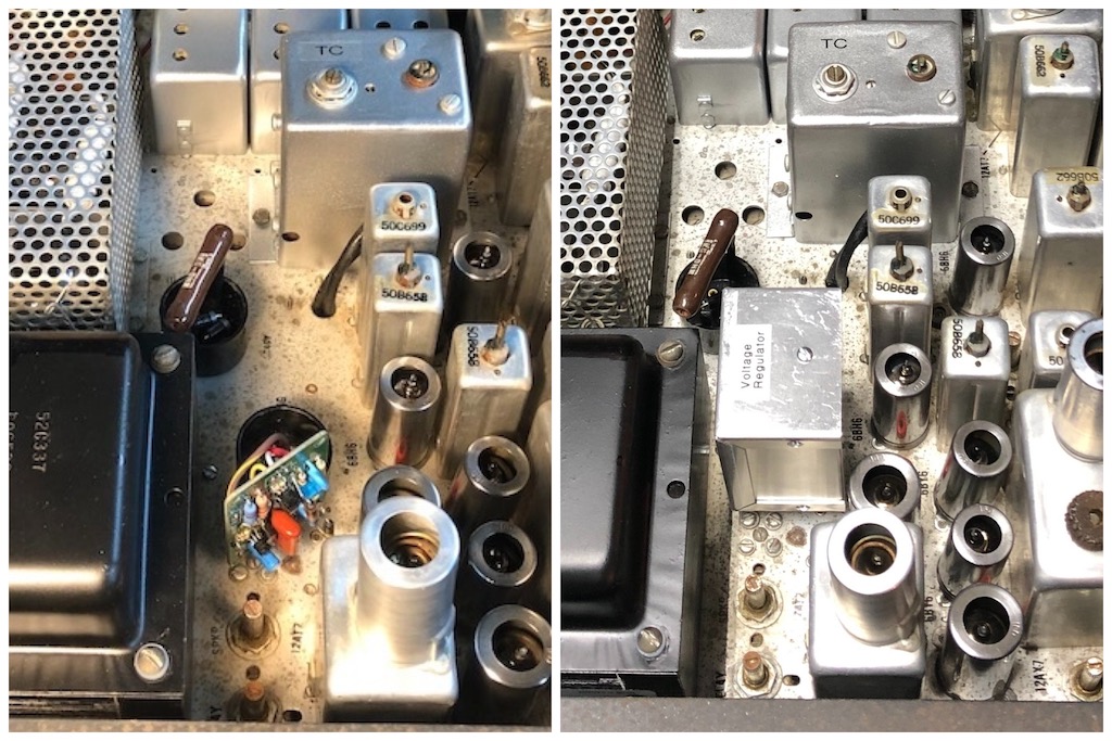
The HV winding produced 430V AC and after a full wave rectification using silicon diodes, it was about 600V DC (430 x 1.414). The transmitter needed 420V HV and 300V LV. The 600V DC was connected to one of the two existing 9H chokes and a filter cap. The regulated output was about 380V ( 600 x 2/pi = 600 x 0.64). Through a voltage dropping resistor, it was fed to a power MOSFET based voltage regulator, which was adjust to output 300V DC. I mounted the regulator PCB on a octal socket and the FET went under the chassis. The HV was also fed to another 9H choke and the resulting 380V was used as HV. This wasn't quite high enough, but the power output was close enought to the spec. The original transformer also had a 75V AC tap for bias. The 300BX has a 50V AC tap, so I modified the bias rectifier to be a voltage doubler and added a couple of resistors to the existing voltage dividor to obtain the correct voltages.
Click to view larger image
![]()
![]()

After replacing the transformer and some more cleaning and parts replacement, the transmitter was producing output. I performed a full alignment per manual. Only the 80m drive/rf/ant were out out alignment. Most other sections were spot on after all those years. During what I thought was final testing, the transmitter stopped keying. The relay control, 12AT7's grid is suppoed to be at 2-3V DC, but it was 0V. The relay actuates at around 64V (6-7mA). With 0V at the grid, it would let 2-3mA to flow. The schematic showed the grid bias is developed by the two small selenium diodes that also function as voltage doubling VOX rectifier.
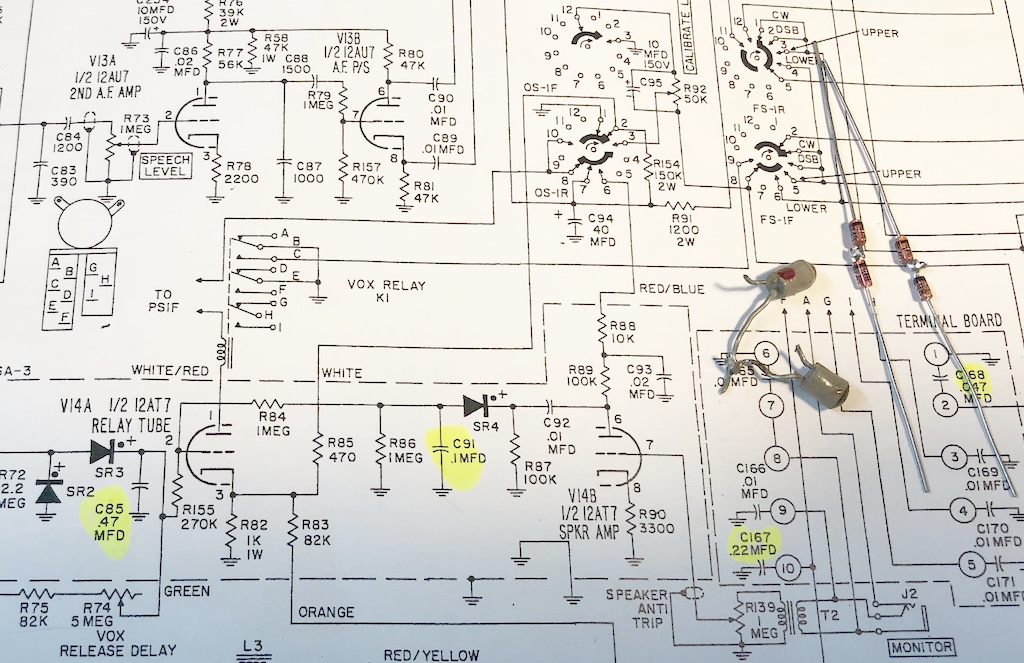
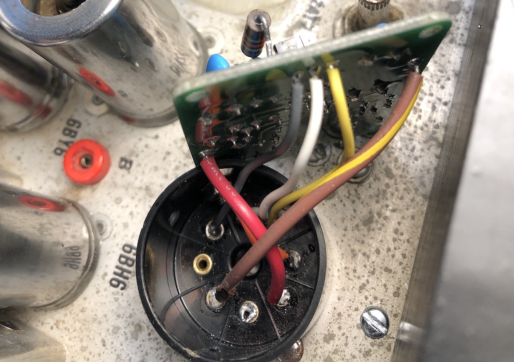
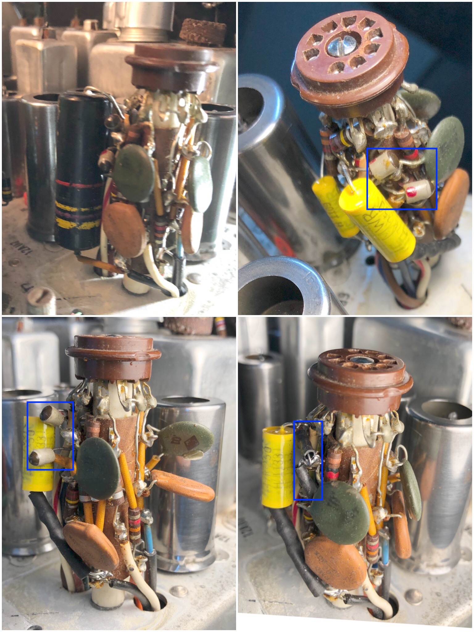
The circuit is actually in the vector assembly inside an aluminum can above the chassis. Opening it revealed two paper capacitors and the two selenium rectifiers, one of which was open. The surviving one had Vf of over 0.9V when measured with my Fluke 27/FM. One silicon diode wouldn't be enough, so I used two serially connected 1N4148 to replace each one.
Since the mic jack was replaced with a 0.210 3-pin one, a PTT circuit line was added for remote TX relay activation.
Finished view of the the bottom side.
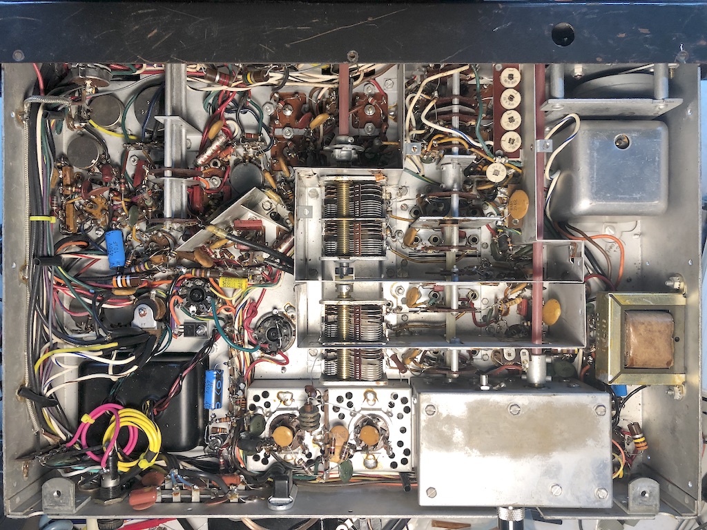
Labels are back on
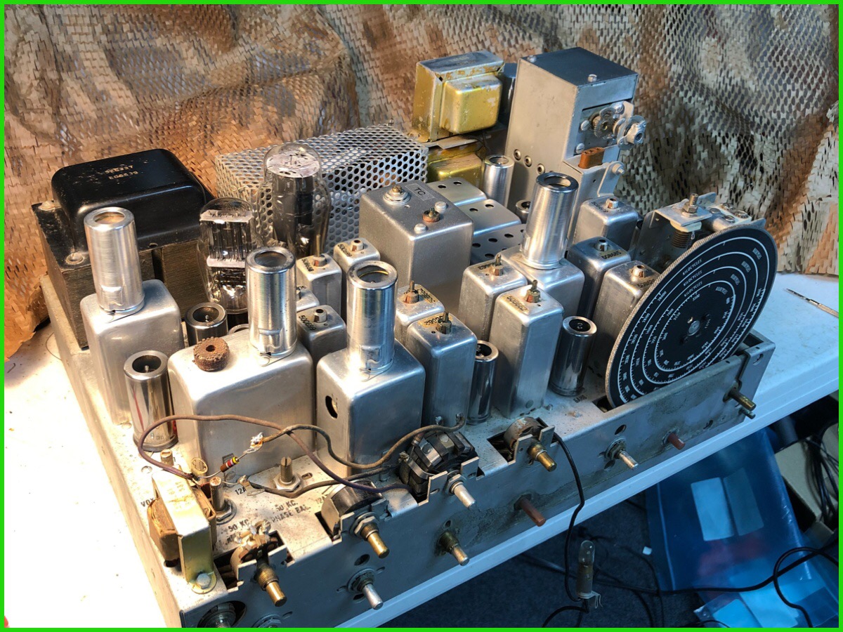
View from top. Rectifier tubes are no longer used.
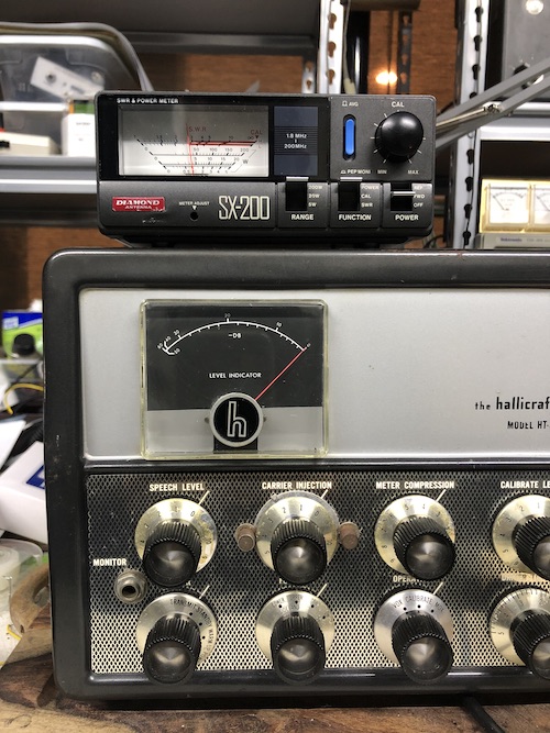
Finished look. It is keyed up in DSB mode and putting out about 35W.
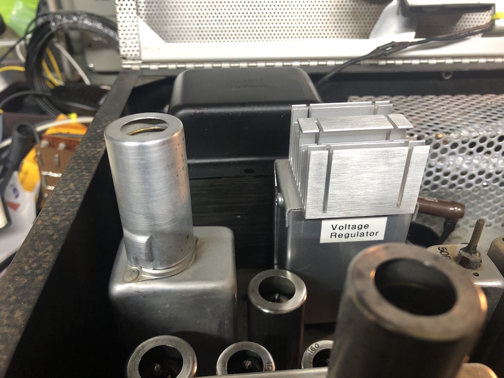
Update (1/6/2020) : The B+ 300V regulator was put in an enclosure. A heatsink was added later.
Update (1/9/2020) : Carrier suppression by the 50kHz LC filter
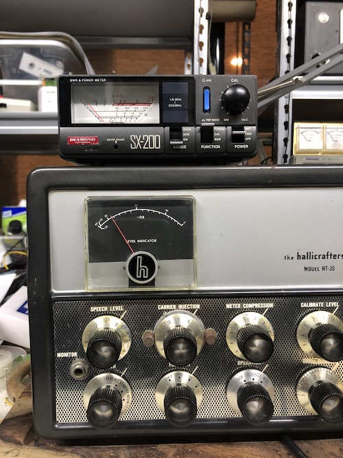
1) 34W Power out with the max carrier injection in DSB mode.
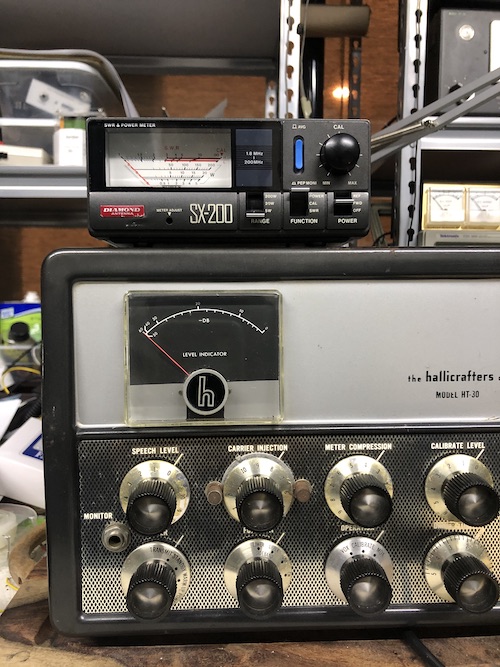
2) At the minimum carrier injection, i.e. modulator is best balanced. More than 20dB suppressed. Less than 100mW output.
3) Switched to USB mode. No detectable output. It is estimated to be at least -50dBc of suppression. Unwanted sideband suppression is a least 40dB.
HT-30 manual
Copyright (C) 2019 Kihwal Lee